


LED CONTROLLER PROGRAMMING
Explore each LED Controller feature below is shipped factory pre-programmed and ready to use. Each section includes a brief description, jumper connections, step-by-step programming instructions, and a short video.
Click here to download the LED Controller Configuration Software.
Primary Modes
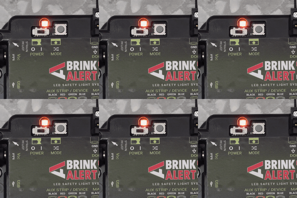
Mode 1
LED Status → Steady
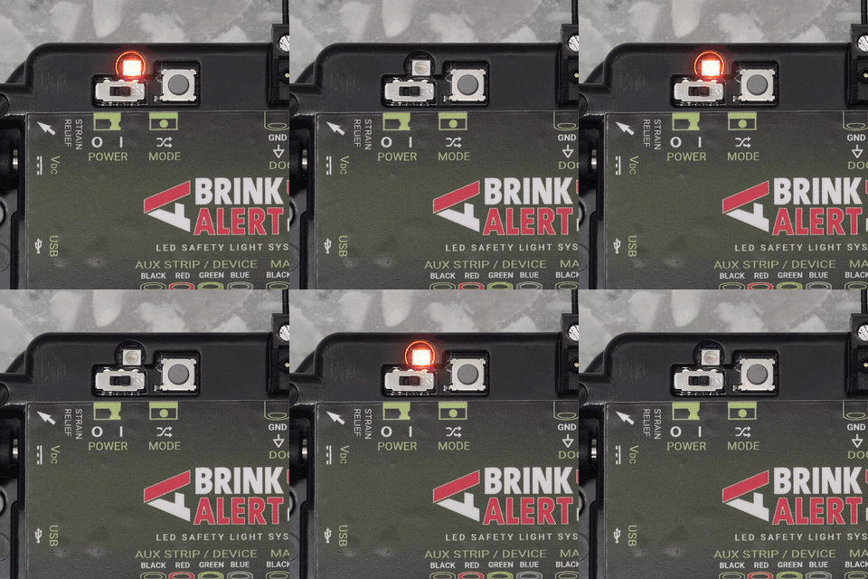
Mode 2
LED Status → Slow Flashing
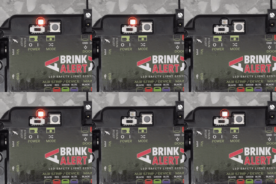
Mode 3
LED Status → Fast Flashing
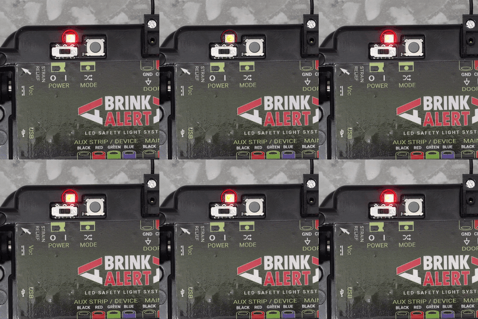
Custom Programming
LED Status → Heartbeat
Controller Type
Door (BDLK)
Dock (LDLK / LDBLK)
LED Aux Behaviour
DOOR
Public Light Mode
Safety warning lights and safety disconnect mode is not shown on the LED Aux strip.
Programming Steps:
Main Green → Open


External Relay Control - Safety
Aux LED port colors can be attached to 24VDC relays in order to control external devices.
Programming Steps:
Aux Red → Open
External Relay Control - Motion
Aux LED port colors can be attached to 24VDC relays in order to control external devices.
Programming Steps:
Aux Red → Safety

Aux Input / Safety
DOOR
Fully Monitored
Monitored mode detects a heartbeat in both the "beam blocked" and "unblocked" states.
Programming Steps:
Main Blue → Safety & Close & Open

Safety Disconnect Warning:
yes
Non-monitored, Basic
Supports simple on / off signa
Programming Steps:
Main Blue → Safety & Close

Half-monitored
Supports a heartbeat greater than 10 Hz when the safety beam is not broken.
Programming Steps:
Aux Red → Open

Aux Input / Pre-announce
DOOR
Toggle Pre-Announce Signal Input
Pre-announce input to replace the default Safety function
Programming Steps:
Main Red → Open

Enable Timed Pre-Announce
LEDs will flash amber after green has been shown for a programmed amount of time
Programming Steps:
Main Blue → Safety

Method of Operation:
Time
Aux Input / Delayed Door Close
DOOR
Enable the delayed door input on Safety
When enabled, a momentary signal on Safety / Preannounce while the door is opened will cause the AUX BLUE output to turn on after about 8 seconds, the signal itself lasting for about 2 seconds, which will give the door a command to close. To change the delay length of time, use the programming command below. By default timed preannounce is not enabled, so this will also need to be enabled seperately.
Programming Steps:
Main Green & Main Blue → Close
Delay time before the door close command is issued
This will determine how long the door should stay opened from the moment the button is pressed until the door is given the command to close.
-
Push and hold down button for length of time desired
-
If the controller is turned off before timer configuration, the default time is 8 seconds.
Programming Steps:
Main Red & Main Green → Safety
Method of Operation:
Time

Controller Options
DOOR
Set threshold to 15 V
Select the inputs to affect with Ground before using this option
Programming Steps:
Main Blue → Safety
Main Red → Open

Set threshold to 8.5 V
Select the inputs to affect with Ground before using this option
Programming Steps:
Main Red & Main Green→ Close

Set threshold to 2.5 V
Select the inputs to affect with Ground before using this option
Programming Steps:
Main Blue → Safety
Main Green → Open

Set threshold to 0.7 V
Select the inputs to affect with Ground before using this option
Programming Steps:
Main Blue → Safety
Main Red → Close

Set to a variable threshold
Select the inputs to affect with Ground before using this option (automatic detection)
Programming Steps:
Main Blue → Safety
Main Green → Close

Disable transition effect
Disables the transition effect of both LED outputs
Programming Steps:
Main Blue → Safety & Open

Configure Safety Delay
Timer for safety beam when blocked when the door is opened before the safety triggers.
Programming Steps:
Main Red & Main Blue→ Close

Disable Mode Button
Disable Mode Button and ignores any inputs
Programming Steps:
Black → Safety & Close

Enable Mode Button
Re-enables mode button after disabling it.
Programming Steps:
<No jumpers>

Enable PWM Detection
Before entering this command, select the ports you want to affect with inversion (GND). This will enable PWM detection for a given port.
Programming Steps:
Main Red & Main Blue → Safety

Disable negative voltage detection
Before entering this command, select the ports you want to affect with inversion (GND). This will disable negative DC detection for a given port
Programming Steps:
Black → Close
Main Red → Safety

LED Behavior
DOOR
Configure brightness for Main
Change the brightness of the Main LED
Programming Steps:
Main Green → Close

Configure brightness for Aux
Change the brightness of the Aux LED
Programming Steps:
Main Blue → Close

Configure brightness for Main & Aux
Change the brightness of the Main & Aux LED
Programming Steps:
Main Green &
Main Red → Open

Controller Options
DOCK
Disable Mode Button
Disable the ability to change modes
Programming Steps:
Black → Open & Aux


LED Behavior Options
DOCK
Enable Outside LED Strip
ables outside LED to be opposite of inside LED Timed delay of green before shown outside (5 sec)
Programming Steps:
Restraint Green → Leveler Red
